Use Case for L2TPv3
Written by Rio Zavarce, Principal Consulting Engineer, Aspire Technology Partners
How to maintain Access to All IT Systems During a Data Center Migration
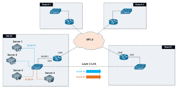
Maintaining access to all IT systems during a data center migration poses a technical limitation: duplicate IP subnets cannot exist in two geographically-disperse locations simultaneously. It is possible, however, to implement a Layer 2 link via Ethernet to connect the old and new locations, allowing virtual local area networks (VLANs) and IP subnets to extend between the two data centers, making them behave as if they existed within the same physical location.
What is Layer 2 Tunnel Protocol Version 3?
Layer 2 Tunneling Protocol Version 3 (L2TPv3) is a point-to-point layer two session protocol that runs over an IP tunnel, enabling you to tunnel Layer 2 protocols like Ethernet over any IP network. This allows L2TPv3 to simulate a virtual Ethernet link between two points – like the data centers in the example diagram below – by “bridging” all VLANs across an IP network, such as the Internet or a Multiprotocol Label Switching (MPLS) telecom network.
Layer 2 Tunneling Protocol uses IP protocol 115 and can be encapsulated directly into IP. This includes encapsulating Ethernet frames into L2TVPv3 and the latter into IP. Once data has been encapsulated into IP, it can then travel over any IP network.

Layer 2 Tunneling Protocol Version 3 (L2TPv3) via Layer 2 Ethernet
During an initial test of the L2TPv3 virtual tunneling technique to connect two data centers, WAN providers were unable to make a temporary Ethernet link available during the migration.
As a result of the absence of a Layer 2 line, all IP hosts within every subnet would need to migrate simultaneously, adding a layer of complexity and preventing a gradual migration over time. Further, migrating whole subnets could similarly require simultaneously moving any network services contained within the same IP subnet.
This situation could significantly increase the risk of downtime of more than one critical network-dependent service.
The perfect example of when L2TPv3 virtual tunneling came to the rescue
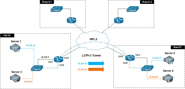
This is a perfect example of how the L2TPv3 virtual tunneling technique can come to the rescue. As in the diagram below, MPLS edge routers at each data center that were capable of handling L2TPv3 and hosting an available interface that could be configured and used to capture all VLANs – were employed to encapsulate VLAN data into IP for routing across the MPLS cloud from the old data center to the new data center.
Layer 2 Tunneling Protocol Version 3 (L2TPv3) via MPLS

Layer 2 Tunneling Protocol Version 3 (L2TPv3) via MPLS
As demonstrated in the above diagram, the existing interface on VLAN 5, G0/1, continued to handle bidirectional traffic between branches and the old Data Center over MPLS. Similarly, the new interface G0/2 was configured as the source of Ethernet frames (VLANs) to be encapsulated into IP to tunnel that VLAN traffic over to the new data center.
Once the L2TPv3 tunnel was established, Server 2 on VLAN 10 was able to move to the new data center while maintaining its original IP address. Likewise, Server 4 on VLAN 20 was transferred to the new data center and brought back online with the same IP address. VLANs 10 and 20 were effectively extended over a Layer 3 network. This level of flexibility allows for gradual server migration to the new data center while minimizing downtime.
Maintaining access to all IT systems during a data center migration is critical–and possible with a little innovation
Maintaining access to all IT systems during a data center migration is critical. Technical limitations, physical location logistics, and coordination with multiple parties – IT staff, WAN providers, and solution providers – imposes great challenges.
Fortunately, a little innovation and the use of unrelated but useful technologies can help solve specific project requirements. The beauty of understanding all the technologies available during a large project is that you can put them to work together to solve a problem smoothly and creatively.
About the Author
Alirio (Rio) Zavarce possesses over 24 years of technical network consulting experience in LAN, WAN, datacenter, and security technologies. His broad range of experience in architecting and implementing advanced technology solutions includes working with clients across multiple verticals including manufacturing, financial services, real estate, higher education, and healthcare. Rio holds numerous industry certifications including Cisco Certified Internetwork Expert (CCIE) Routing and Switching.
Read more from this author:
How to Solve No Boolean Tracking Support on Cisco ASA
References
(1) L2 Bridging Across an L3 Network Configuration Example


